


You’re about to explore Electronic Design Automation (EDA), a key tool for making complex electronic systems. EDA software lets you create, simulate, and test electronic designs before they’re made. This helps avoid mistakes and makes the design process better.
With EDA software, you can design things like printed circuit boards (PCBs), integrated circuits, and microprocessors. It’s all about using computer-aided design to make complex electronic systems.
Understanding Electronic Design Automation (EDA) Software
Exploring EDA software reveals its power to change your design workflow. It has moved from manual to automated processes. This makes design faster and more efficient.
Definition and Core Functions
EDA software is more than a tool. It’s a full platform for design entry, simulation, verification, and manufacturing preparation. It helps you create, analyze, and improve electronic designs quickly.
The main parts of EDA software are:
- Schematic capture: You can make graphical models of your circuits here.
- Simulation tools: These let you test and check your designs before making a real prototype.
- Layout and routing tools: These help you arrange components and connect them on a PCB.
- Verification tools: They make sure your design meets all the needed standards.
| Core Function | Description |
|---|---|
| Design Entry | Creating graphical representations of electronic circuits |
| Simulation | Testing and analyzing designs before physical prototyping |
| Layout and Routing | Placing components and routing connections on a PCB |
| Verification | Ensuring designs meet required specifications and standards |
The Evolution of EDA Tools
EDA tools have grown a lot, from basic CAD systems to complex software. They now handle billions of components. They’ve also become more advanced, with better simulations and easier-to-use interfaces.
Today, EDA software keeps getting better. It’s driven by the need for quicker and more precise designs. Expect to see more artificial intelligence, cloud computing, and collaborative design features.
The History and Development of EDA Software
You are about to explore the fascinating journey of EDA software, from its humble beginnings to its current state.
The earliest EDA tools were developed academically. One notable example is the “Berkeley VLSI Tools Tarball.” These early tools set the stage for today’s advanced EDA software.
Early Beginnings: From Manual Design to Automation
In the early days, designing electronics was a manual process. It was prone to errors and took a lot of time. The introduction of EDA software changed this, making designs more accurate and efficient.
The move from manual to automated design was slow. EDA software evolved to meet the growing needs of the electronics industry.
Modern EDA Software Evolution
Today, EDA software is a powerful tool for complex electronic designs. It has evolved to include features like schematic capture, PCB design, and simulation.
The following table highlights some key milestones in the development of EDA software:
| Year | Milestone | Description |
|---|---|---|
| 1970s | Academic EDA Tools | Early EDA tools, such as the Berkeley VLSI Tools Tarball, were developed academically. |
| 1980s | Commercial EDA Software | The first commercial EDA software emerged, marking a significant shift towards industry adoption. |
| 1990s | EDA Software Advancements | EDA software continued to evolve, with advancements in simulation and verification tools. |
As you can see, the history of EDA software is a story of continuous innovation and improvement.
Types of EDA Software for Electronic Design
EDA software includes many tools for various stages of electronic design. These tools are key for making, testing, and manufacturing electronic systems.
Schematic Capture Software
Schematic capture software helps create and edit circuit diagrams. It lets you design the circuit’s schematic. This design is then used for simulation, testing, and PCB design.
- Enables the creation of complex circuit diagrams
- Often includes libraries of components for ease of use
- Supports simulation and verification of circuit designs
PCB Design Software
PCB design software is vital for designing printed circuit boards. It helps turn your schematic into a physical PCB layout. It considers things like component placement and signal routing.
- Facilitates the transition from schematic to PCB layout
- Includes features for component placement and signal routing
- Supports design rule checks (DRC) for manufacturability
FPGA Design Tools
FPGA design tools are for designing and testing field-programmable gate arrays. These tools help create, simulate, and implement digital logic on FPGA devices. FPGAs are flexible and reconfigurable, used in many electronic systems.
- Allow for the development of complex digital logic
- Support simulation and verification of FPGA designs
- Enable the implementation of designs on FPGA hardware
Knowing the different EDA software types is key for picking the right tools. Whether it’s a simple circuit or a complex system, these tools are essential in the design process.
Key Components of Electronic Design Automation Software
EDA software has three main parts: design entry tools, simulation and verification tools, and layout and routing tools. Knowing these parts is key to using EDA software well in your electronic design work.
Design Entry Tools
Design entry tools help you make circuit diagrams and put your design into the EDA software. They offer a graphical way to draw schematics, enter HDL code, or make other design forms. With these tools, you can quickly get your design idea down and move on to the next steps.
Simulation and Verification Tools
Simulation and verification tools are vital for making sure your designs work right. They let you simulate your circuit’s behavior under different conditions, check its performance, and find issues before making a physical prototype. Simulation software is a big part of this, helping you test and check your designs.
Layout and Routing Tools
Layout and routing tools are key for PCB design. They help you place components and route connections well. A PCB layout tool lets you arrange components on the board, define routes, and make sure your design can be made. These tools are essential for creating a PCB design that can be made.
By knowing and using these main parts of EDA software, you can make your electronic design process smoother. You’ll improve design accuracy and get your products to market faster.
PCB Design Tools and Layout Software
To bring your electronic designs to life, you need to master the use of PCB design and layout software. This software is key for creating complex electronic designs with precision and accuracy.

PCB Layout Fundamentals
Understanding the basics of PCB layout prototyping is vital for designing functional and manufacturable PCBs. You must consider component placement, routing, and design rules. This ensures your PCB works as planned.
- Component Placement: Strategically placing components to minimize signal delay and optimize PCB performance.
- Routing: Creating pathways for signals to travel between components while minimizing interference.
- Design Rules: Establishing rules to ensure your design is manufacturable and meets specific standards.
Advanced PCB Design Features
Advanced PCB design features improve the quality and reliability of your designs. You can use features such as:
- Design Rule Checking (DRC): Automatically checking your design against predefined rules to identify any issues.
- Signal Integrity Analysis: Analyzing your design to ensure signal quality and minimize distortion.
- Thermal Analysis: Evaluating the thermal performance of your PCB to prevent overheating issues.
PCB Design Constraints and Rules
Applying PCB design constraints and rules is key for optimizing your designs for manufacturability. You need to consider:
- Manufacturing Constraints: Understanding the limitations of your manufacturing process to design PCBs that are feasible to produce.
- Design for Manufacturability (DFM): Designing your PCB with manufacturability in mind to reduce production costs and improve yield.
By mastering PCB design tools and layout software, you can create high-quality, reliable PCBs that meet your design requirements.
Circuit Design Software Capabilities
Circuit design software offers a wide range of features. It helps design and simulate different electronic circuits. You can use it to create everything from simple analog circuits to complex digital and mixed-signal systems.
Analog Circuit Design
Analog circuit design is about making circuits for continuous signals. With the right software, you can design and test analog circuits. This ensures they work as needed. Key features include:
- Component libraries with real-world models
- Signal analysis tools for frequency and time-domain analysis
- Support for complex circuit simulations
Digital Circuit Design
Digital circuit design deals with signals that are either on or off. Circuit design software lets you create and test digital circuits. This helps check their function before making them real. Important aspects include:
- Support for HDL (Hardware Description Language) programming
- Simulation tools for testing digital circuit behavior
- Integration with FPGA design tools
Mixed-Signal Design
Mixed-signal design mixes analog and digital parts. It needs special tools and methods. Circuit design software helps design and test these mixed circuits. This ensures they work well together. Key benefits include:
- Unified design environment for both analog and digital components
- Advanced simulation capabilities for mixed-signal circuits
- Support for complex system-on-chip (SoC) designs
Simulation Software in the EDA Ecosystem
Simulation software helps you test and validate your electronic circuit designs. It reduces the risk of costly rework. It’s a key part of the EDA ecosystem, letting you predict how electronic circuits will behave before they’re made.
Circuit Simulation Techniques
Circuit simulation techniques are key for analyzing electronic circuits. You can use them to simulate various aspects of your designs. This includes:
- Transient Analysis: This lets you see how the circuit acts over time. It shows how it responds to different inputs.
- Frequency-Domain Analysis: This method analyzes the circuit’s behavior at different frequencies. It’s important for understanding its performance in various applications.
Thermal and Power Analysis
Thermal and power analysis are vital for ensuring your electronic designs are reliable and perform well. Simulation software helps you:
- Analyze Power Consumption: You can see how much power your circuit uses under different conditions.
- Thermal Analysis: It helps spot thermal issues that could harm your circuit’s performance and reliability.
Signal Integrity Analysis
Signal integrity analysis is key for spotting issues with signal quality and timing in your designs. Simulation software lets you:
- Analyze Signal Quality: Make sure your signals aren’t affected by noise, attenuation, or distortion.
- Timing Analysis: Check that your signals are properly synchronized. This is vital for your circuit’s correct operation.
FPGA Design Software and Hardware Description Languages
You use FPGA design software to design and test field-programmable gate arrays. These are integrated circuits that can be programmed and reprogrammed after manufacturing. This software is key for developing digital circuits using FPGAs. It lets you describe, simulate, and implement complex digital systems.
HDL Programming and Synthesis
HDL programming is a key part of FPGA design. You use hardware description languages like VHDL or Verilog to describe digital circuits. This involves writing code that defines the circuit’s functionality. The code is then synthesized into a netlist that can be mapped onto the FPGA device.
HDL programming needs a good grasp of digital logic and the HDL’s syntax. You must design and test your HDL code well. This ensures it accurately describes the circuit behavior and meets performance needs.
FPGA Implementation and Testing
After synthesizing your HDL code, the next step is FPGA implementation. This involves mapping the synthesized netlist onto the FPGA device. You place and route the design, ensuring it meets timing and resource constraints of the FPGA.
Once the design is implemented, you need to test it. This means creating testbenches and simulating the design under various conditions. You can then download the design to the FPGA device. This lets you perform hardware testing to validate its performance in real-world conditions.
Popular EDA Software Platforms in South Africa
In South Africa, designers can pick from many EDA software options. These options range from commercial to open-source, each with its own benefits.
Commercial EDA Solutions
Commercial EDA software comes with full tool suites for electronic design. It also offers professional support and training. Some top commercial EDA solutions include:
- Synopsys: Known for its advanced design and verification tools, Synopsys offers a wide range of EDA software solutions.
- Cadence: Cadence provides a broad portfolio of EDA tools for IC design, PCB design, and more.
- Altium: Altium is popular among PCB designers for its user-friendly interface and powerful design capabilities.
These commercial solutions are often chosen by professionals and big companies. They are known for their reliability and wide range of features.
Open-Source EDA Alternatives
For those on a tight budget or working on small projects, open-source EDA tools are a great choice. They offer good functionality without the high cost. Some notable open-source EDA tools include:
- KiCad: KiCad is a widely-used open-source EDA tool for PCB design, known for its ease of use and compatibility with various operating systems.
- gEDA: The gEDA project provides a suite of open-source EDA tools for schematic capture, simulation, and PCB design.
Open-source EDA tools are great for hobbyists, students, and small businesses. They are free and supported by a community.
When picking an EDA software platform, think about your needs, budget, and support needs. Both commercial and open-source options fit well in South Africa’s electronics design world.
EDA Software for Different Skill Levels
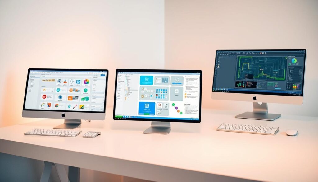
Finding the right EDA software can greatly improve your design work, no matter your skill level. There are many tools available, from easy-to-use options for beginners to advanced software for pros.
Beginner-Friendly EDA Tools
If you’re new to electronic design, beginner-friendly EDA tools are perfect for you. They have simple interfaces that make designing easier. Some top picks for beginners include:
- Tools with drag-and-drop functionality
- Software with built-in tutorials and guides
- Applications that offer real-time feedback and error checking
These tools help beginners grasp the basics of electronic design. They make learning fun and less stressful.
Professional-Grade EDA Software
For seasoned designers tackling tough projects, professional-grade EDA software is the way to go. It has advanced features for complex designs and precise manufacturing. Key features of these tools include:
- Advanced simulation and analysis capabilities
- Support for complex design rules and constraints
- Integration with other design and manufacturing tools
Choosing the right EDA software based on your skill level can boost your design efficiency. It helps you get better results.
The PCB Layout Tool Workflow
Creating functional PCBs involves a key workflow. It starts with schematic capture, where you draw a circuit diagram. This is done using schematic capture software.
From Concept to Schematic Capture
In the schematic capture stage, you define your circuit’s parts and how they connect. It’s a blueprint for your PCB design. You’ll use software to draw a detailed diagram, making sure all parts are right and connected.
From Schematic to PCB Layout
Next, you move to the PCB layout stage. Here, you place components on the board and connect them. It’s important to plan well to make sure the PCB can be made and works right.
Manufacturing Output Generation
The last stage is making files for manufacturing. You’ll create Gerber files and assembly drawings. These are needed for making and putting together the PCB.
Here’s a quick overview of the workflow:
| Stage | Description |
|---|---|
| Schematic Capture | Create a circuit diagram using schematic capture software. |
| PCB Layout | Place components and route connections on the PCB. |
| Manufacturing Output | Generate Gerber files and assembly drawings for fabrication. |
By knowing and following this workflow, you can design and make PCBs that fit your project’s needs.
Integrating EDA Software with Manufacturing Processes in South Africa
To ensure seamless production, you must integrate your EDA software with the manufacturing processes used in South Africa. This integration is key for producing PCBs that meet local standards and requirements.
Design for Manufacturing (DFM)
Design for Manufacturing (DFM) is a critical aspect of PCB design. It involves creating designs with manufacturability in mind. By applying DFM principles, you can reduce errors, improve yields, and lower costs.
Key DFM considerations include:
- Minimum trace widths and spacing
- Drill size and placement
- Component placement and orientation
- Copper pouring and via usage
Optimizing your design for manufacturability ensures efficient and effective PCB production in South Africa.
Gerber File Generation and Local PCB Fabrication
After designing your PCB with DFM principles, the next step is to generate fabrication files. The Gerber file format is the industry standard for PCB fabrication. Your EDA software should generate Gerber files with all necessary fabrication information.
Gerber file generation exports the PCB design data into a format readable by fabrication equipment. This includes files for copper layers, solder mask, silkscreen, and drill data.
| Gerber File Type | Description |
|---|---|
| Copper Layer | Contains the copper trace and pad information |
| Solder Mask | Defines the areas where solder mask should be applied |
| Silkscreen | Includes text and graphics for component identification |
| Drill Data | Specifies the location and size of holes to be drilled |
By ensuring your EDA software can generate accurate Gerber files, you can confidently send designs to local PCB fabricators in South Africa. This ensures your products will be manufactured correctly.
Cost Considerations for EDA Software
To budget for EDA software, look at different costs and licensing options. Knowing these will help you choose what’s best for your business.
Licensing Models and Pricing Structures
EDA software vendors have various licensing models and prices. The main ones are:
- Perpetual Licenses: You pay once and use the software forever. But, updates and support might cost extra.
- Subscription-Based Models: You pay a fee, usually monthly or yearly. This includes updates and support.
- Floating Licenses: These can be shared by many users. The number of users depends on the license count.
Think about your team size, project needs, and budget when picking a model. For example, a subscription might be better for projects that change often. A perpetual license could save money for long-term projects.
Return on Investment for South African Businesses
For South African businesses, understanding EDA software ROI is key. ROI can be boosted by better design efficiency, lower costs, and higher quality products.
To figure out ROI, look at:
- Cost Savings: Less labor cost because of faster, more accurate design.
- Increased Productivity: Faster design means products hit the market sooner.
- Improved Accuracy: Better designs mean less need for costly fixes or rework.
By examining these points, South African businesses can see the ROI of EDA software. This helps make smart investment choices.
Learning Resources for EDA Software in South Africa
South Africa has many resources for learning EDA software. You can find everything from formal training to online forums. These tools help you improve your skills and keep up with new EDA software trends.
Training Programs and University Courses
There are many training programs and university courses for EDA software. These are offered by technical schools and universities all over South Africa. For example, some universities teach about schematic capture, PCB design, and FPGA design in electronic design automation.
These programs are great for both newbies and those looking to improve. They include practical training with top EDA software tools. This way, you get real-world experience.
Online Communities and Local Support Groups
There’s also online communities and local support groups to explore. These places let you ask questions, share tips, and learn from others using EDA software. You can join Reddit and Stack Overflow forums to connect with more people.
Local groups, often set up by industry associations or user groups, are also valuable. They let you meet other professionals and learn about using EDA software effectively. You can also find workshops and seminars on specific EDA software topics.
By mixing formal training with online communities and local groups, you can really get to know EDA software. This will boost your career in electronic design.
The Future of Electronic Design Automation: Trends and Innovations
The world of EDA software is changing fast, thanks to AI and machine learning. These technologies are making EDA tools better at designing and simulating. You’ll see more automated design, better simulations, and easier teamwork in the future.
AI-driven design automation is becoming a big trend in EDA software. It uses machine learning to make design processes faster and more accurate. This means you’ll get your designs done quicker and with higher quality.
EDA software is also getting better at making things easier for users and working with other systems. New tools are designed to work well with other systems, making it easier to go from design to production. This is great for businesses in South Africa that want to use the latest tech to stay ahead.
As EDA software keeps getting better, you’ll see new features that meet today’s design challenges. Keeping up with these changes will help you use the latest EDA software to its fullest.
FAQ
What is EDA software used for?
EDA software helps design, simulate, and test electronic systems. This includes printed circuit boards (PCBs), integrated circuits, and microprocessors. It’s used before they are made.
What are the core functions of EDA software?
EDA software’s main functions are design entry, simulation, verification, and manufacturing prep. It lets you create and test electronic designs accurately.
What is the difference between schematic capture software and PCB design software?
Schematic capture software is for making and editing circuit diagrams. PCB design software is for designing and laying out PCBs, including where to place components and how to route them.
What is FPGA design software used for?
FPGA design software is for designing and testing field-programmable gate arrays. It uses hardware description languages (HDLs) like VHDL or Verilog.
What are the benefits of using simulation software in EDA?
Simulation software lets you predict how electronic circuits will behave before they’re made. This reduces errors and improves design accuracy.
What is design for manufacturing (DFM), and why is it important?
DFM means designing PCBs with manufacturing in mind. It reduces errors and improves yields. It’s key for optimizing designs for local PCB fabrication.
What are the different licensing models for EDA software?
EDA software vendors offer various licensing options. These include perpetual licenses and subscription-based models. Each has its costs and benefits.
What are the advantages of using open-source EDA alternatives?
Open-source EDA alternatives, like KiCad, are cost-effective. They offer a good alternative to commercial EDA solutions.
How can I learn more about EDA software and improve my skills?
You can learn more about EDA software through training programs and university courses. Online communities and local support groups also provide learning opportunities and knowledge sharing.
What are the future trends and innovations in Electronic Design Automation?
EDA software is getting better with AI and machine learning. These advancements make design processes more efficient and accurate. They’re shaping the future of the industry.
What is the role of Gerber file generation in PCB fabrication?
Gerber file generation is key in manufacturing. It provides the necessary files for PCB fabrication. This ensures your designs are made accurately.
How does EDA software support different skill levels?
EDA software is for all skill levels. Beginner-friendly tools have graphical user interfaces. Professional-grade software offers advanced features and capabilities.